


Product Details
+
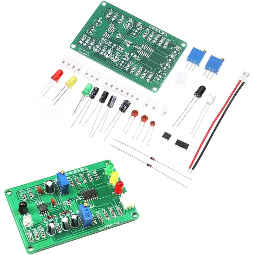
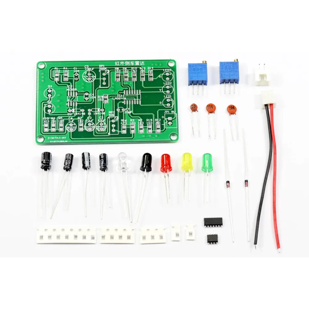
This DIY infrared parking sensor kit includes various components that you will need to assemble on the provided PCB.
Resistors: Identify the resistors based on their color codes and place them in the designated spots on the PCB.
Capacitors: Place the electrolytic capacitors (observe polarity) and ceramic capacitors in their respective positions.
Diodes: Ensure the correct orientation (check the stripe indicating the cathode).
Potentiometers: Solder these into the place where indicated.
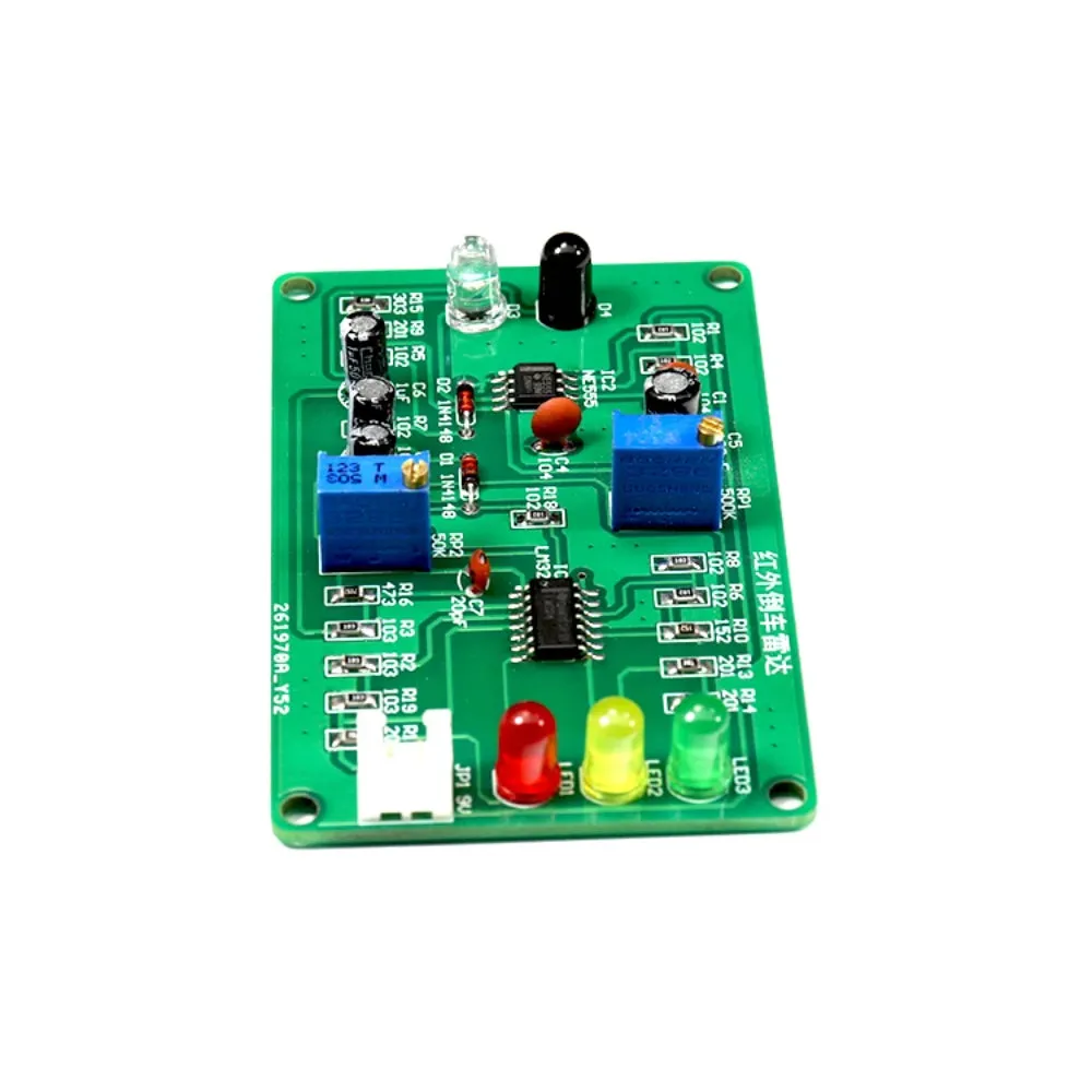
LEDs: Insert the LEDs, ensuring the correct orientation (the longer leg is the anode).
Infrared LEDs and Photodiodes: Place these in the correct positions as per the instructions.
ICs: Carefully place the ICs in their sockets if provided, otherwise directly solder them, ensuring the correct orientation.
Soldering: Solder each component carefully, ensuring there are no cold joints or bridges. Trim the excess leads after soldering.
Connecting Wires and Connectors: Solder the connectors for the power supply and any other connections. Connect the wires for the power supply and sensors.
Powering Up and Calibration: Connect the power supply. Adjust the potentiometers to calibrate the sensors if necessary.
Assembly Steps::
Identify and Place Components:Resistors: Identify the resistors based on their color codes and place them in the designated spots on the PCB.
Capacitors: Place the electrolytic capacitors (observe polarity) and ceramic capacitors in their respective positions.
Diodes: Ensure the correct orientation (check the stripe indicating the cathode).
Potentiometers: Solder these into the place where indicated.
LEDs: Insert the LEDs, ensuring the correct orientation (the longer leg is the anode).
Infrared LEDs and Photodiodes: Place these in the correct positions as per the instructions.
ICs: Carefully place the ICs in their sockets if provided, otherwise directly solder them, ensuring the correct orientation.
Soldering: Solder each component carefully, ensuring there are no cold joints or bridges. Trim the excess leads after soldering.
Connecting Wires and Connectors: Solder the connectors for the power supply and any other connections. Connect the wires for the power supply and sensors.
Testing:
Once all components are soldered, visually inspect for any potential issues like solder bridges. Use a multimeter to check for continuity and correct voltages.Powering Up and Calibration: Connect the power supply. Adjust the potentiometers to calibrate the sensors if necessary.
Components
- PCB (Printed Circuit Board)
- Capacitors (Electrolytic and Ceramic)
- Resistors
- Infrared LEDs (Likely the black ones)
- Photodiodes or Phototransistors (Likely the transparent ones)
- Standard LEDs (Red, Green, Yellow)
- Potentiometers
- Diodes
- ICs (Integrated Circuits)
- Connectors and Wires
Package Includes
- 1 x Infrared Reversing speed indicator electronic assembly and debugging DIY


